
Quick Answer
Evaluate photoelectric sensor suppliers by their ability to prove application fit, maintain consistent production, control changes, and support the machine throughout its service life. Begin with a written detection requirement covering targets, surfaces, distance, speed, mounting, environment, and PLC compatibility. Request model-specific documents and test representative samples under production conditions. Score suppliers only after mandatory technical requirements pass. Then compare traceability, manufacturing controls, delivery commitments, engineering support, and total installed cost. A low quotation or successful tabletop demonstration is insufficient evidence for an OEM platform. Approval should connect an exact part number and revision to a documented validation result and supply agreement.
Key Takeaways
• Define the detection task before requesting supplier recommendations or prices.
• Test the darkest, shiniest, smallest, and most difficult acceptable targets.
• Verify response time through the controller, not only at the sensor indicator.
• Require evidence tied to the ordered model, manufacturing site, and revision.
• Use a scored comparison alongside mandatory pass or fail requirements.
• Include change notification, replacement setup, and lifecycle support in qualification.
Why OEM supplier evaluation starts with the machine
An OEM purchasing team receives three quotations for a compact photoelectric sensor. All promise the required distance and compatible output, but the machines must run different packages, installation geometries, and customer cleaning routines. The purchasing risk is not simply choosing the wrong brand. It is approving a device without defining the conditions under which detection must remain reliable.
Public manufacturer data show why model-level comparison matters. OMRON lists a 0.5 ms response time for models in its E3FA/E3RA/E3FB/E3RB specifications, while its technical terminology separates output response from the optical event that initiates it. [1, 2] A supplier evaluation must connect such data to available target dwell time and the actual controller input path. Photoelectric sensor suppliers should be assessed on evidence that closes those application questions.
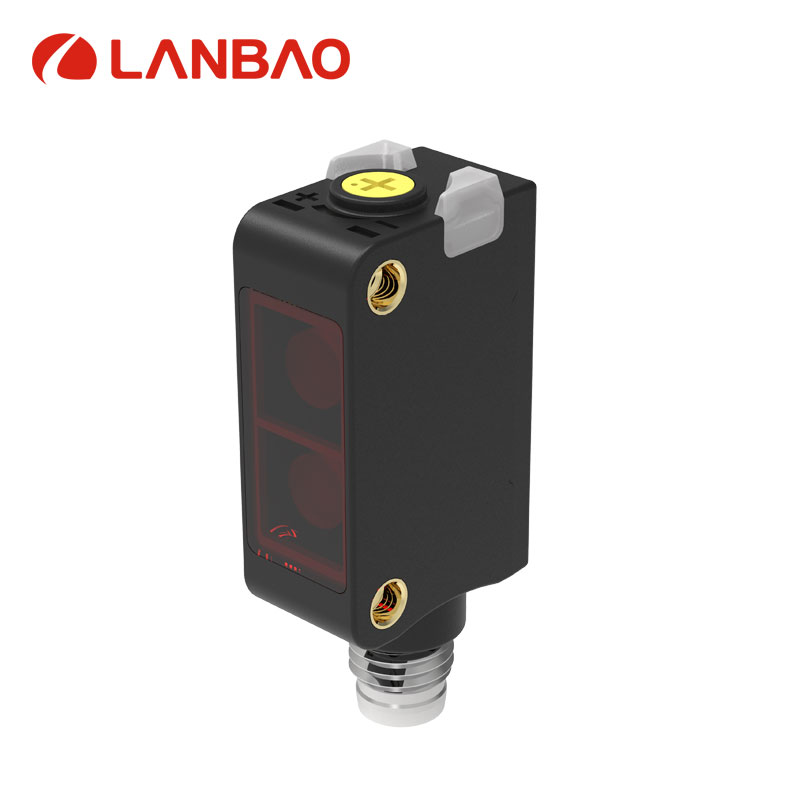
Figure 1. Lanbao PSEP series product image from the official website. This diffuse sensing family is an example candidate, not a universal replacement for other optical modes. Source [3].
Turn the application into a written requirement
Start with a short application brief shared by engineering, purchasing, quality, and service. Describe what must be detected and what must be ignored. Include actual samples or controlled images, dimensional drawings, accepted colors, surface finishes, transparency, mounting space, working distance, and possible background objects.
Define the operating envelope. Record minimum and maximum speed, smallest target, smallest gap between targets, vibration, ambient light, contamination, temperature, cleaning method, and cable movement. State whether the output is used for counting, positioning, presence detection, or process interlocking because those tasks may require different timing and failure handling.
Separate essential requirements from preferences. A missed transparent bottle may be unacceptable, while a preferred connector orientation could be negotiable. Specify measurable acceptance conditions wherever possible. “Reliable in dust” is difficult to verify; a documented contamination condition, cleaning interval, and permitted detection behavior create a useful test discussion.
Avoid treating ordinary automation sensors as personnel protection devices. If the application includes a safety function, route that requirement through the appropriate machine safety assessment and select equipment with the necessary documented capability. A standard switching output and a protective housing do not establish safety suitability.
Check whether the proposed optical mode fits
A credible supplier should explain why the proposed sensing principle fits the target and installation. Through-beam arrangements place emitter and receiver on opposite sides. Retroreflective arrangements use a reflector. Diffuse sensors receive light reflected by the target itself. Background suppression adds distance discrimination, subject to the particular design's limits. OMRON's technical guide provides an overview of these operating principles. [4]
The choice changes installation cost and robustness. Through-beam sensing requires access and wiring on two sides. A reflector adds mounting and cleaning needs. Diffuse sensing can simplify installation but makes target reflectivity and background conditions especially relevant. Transparent objects require application-specific selection rather than an assumption that every optical sensor will detect them consistently.
Ask for the minimum detectable object, beam or spot dimensions at the working distance, dead zones, background limitations, and alignment tolerance. The supplier should identify unfavorable conditions as well as favorable ones. An explanation of a limitation is often more useful than a broad statement that the sensor detects every material.
Compare detection margin instead of maximum range alone
The maximum published distance is usually linked to a reference target or reflector. Ask what changes when the real target is dark, angled, reflective, partially transparent, or smaller than the reference. Test the entire allowed distance range, including close positions where some optical arrangements behave differently.
Banner explains excess gain as the received optical energy relative to the switching threshold and describes its relevance when dust, moisture, or other contaminants attenuate the signal. [5] Request the applicable curve or an equivalent margin assessment at the proposed distance. Do not transfer a general excess-gain recommendation blindly to transparent-object sensing, where the small change in received light must also be resolved.
A useful demonstration includes the worst accepted part and an unfavorable background. Ask the supplier to show the failure boundary and explain the reserve available within the approved operating envelope. That makes a recommendation more credible than a single successful trigger at a convenient distance.
Verify timing and electrical integration
Consider an illustrative package tab that is 4 mm wide and travels at 2 m/s. Its geometric passage time is 2 ms. A candidate's nominal 0.5 ms response looks promising, but the remaining system may add filtering, scan delay, communication delay, or trigger uncertainty. This calculation screens the concept; it does not certify the installed machine.
Measure the output waveform and the signal recognized by the PLC. Test both activation and reset, because short gaps can disappear even if individual targets are detected. Agree whether pulse stretching is permitted and whether it affects downstream counting or reject timing. Record controller filter settings with the sensor configuration.
Confirm NPN or PNP compatibility, normally open or normally closed behavior, light-on or dark-on configuration, pin assignment, operating voltage, load current, and cable specification. When replacing an incumbent, compare connector function rather than appearance. A mechanically interchangeable sensor can still require wiring or software changes.
Assess supplier capability using verifiable evidence
A quality certificate can support a supplier review, but it does not prove that a particular sensor passes an application. Verify the certificate's organization, site, scope, validity, and issuer. Separately request the product documentation appropriate to the destination market and machine requirements. Claims such as CE marking, UL recognition, or IP protection should be checked against the exact relevant model and supporting records.
During a manufacturing review, follow one product from incoming components to final test. Ask how optical alignment, switching thresholds, electrical outputs, and identification are controlled. Request examples of test records and calibration management. The goal is to understand how the supplier detects variation and prevents an unapproved process change from reaching the OEM.
Traceability should connect a supplied batch or serial number to manufacturing and test information. Ask the supplier to demonstrate that retrieval using a real sample identifier. A documented system is more convincing when the requested record can actually be found and interpreted.
|
Evaluation category |
Proposed weight |
Evidence required for a high score |
|
Application performance |
35% |
Passed target and environmental test matrix |
|
Manufacturing and quality |
20% |
Traceability, test records, controlled processes |
|
Engineering support |
15% |
Reproducible troubleshooting and complete documentation |
|
Delivery and continuity |
15% |
Capacity evidence, lead-time agreement, continuity plan |
|
Installed lifecycle cost |
10% |
Hardware, installation, validation, service cost model |
|
Change management |
5% |
Written notification and requalification procedure |
This weighting is a proposed OEM evaluation tool, not an industry ranking. Score each category from zero to five and calculate the weighted total as the sum of weight multiplied by score divided by five. A score of four in the 35% category contributes 28 points. Apply mandatory requirements first: a high commercial score must not compensate for failed detection or missing required documentation.
Run samples through a staged qualification process
Request the exact production-intent part number, firmware or configuration revision where relevant, cable, connector, and accessories. Record whether the samples were specially prepared. Samples from more than one production lot can help reveal variation, although the appropriate quantity depends on risk and availability.
|
Qualification stage |
Scope |
Suggested approval gate |
|
Document review |
Datasheet, wiring, drawings, model evidence |
No unresolved mandatory requirement |
|
Bench evaluation |
Target extremes and mounting boundaries |
Agreed detection and reset margins demonstrated |
|
Machine trial |
Full speed, controller, adjacent sensors |
No unexplained counting or trigger failures |
|
Pilot production |
Representative shifts and maintenance |
Stable results with traceable issue resolution |
|
Production release |
Frozen model and supply conditions |
Signed validation and change-control records |
1. Define targets, operating extremes, and acceptance criteria before receiving samples.
2. Run controlled bench tests and retain successful and failed conditions.
3. Integrate the sensor into the actual machine and capture timing evidence.
4. Repeat after a technician performs a normal replacement or adjustment.
5. Review the pilot results jointly before committing to platform-wide release.
Use a trial length that reflects the failure risk. Zero observed failures in a small test does not establish a zero failure rate. For illustration, zero failures across 10,000 independent, representative opportunities gives a rough one-sided 95% upper bound of about 3/10,000, or 300 failures per million opportunities, using the rule of three. Real cycles may be correlated, and a trial that never includes the difficult target does not represent production risk.
Evaluate support by asking for a troubleshooting exercise
Give shortlisted suppliers the same realistic failure scenario, such as false triggers from a shiny background or missed dark parts after contamination. Ask for a test plan, requested measurements, and a proposed corrective action. Evaluate whether the answer distinguishes optical, electrical, mechanical, and controller causes.
Useful support produces a reproducible setting or engineering change with a reason. Record who owns application questions, response expectations, escalation, and failure analysis. Request instructions that a service technician can follow without relying on the salesperson who handled the original order.
For global machines, consider documentation language, spare availability, connector sourcing, and setup consistency across sites. A model that requires delicate manual adjustment may increase service burden even if the purchase price is attractive. Include replacement teach-in and verification time in the evaluation.
Review continuity and the total installed cost
Ask for written lead-time assumptions, minimum order quantities, packaging, shipment identification, and capacity arrangements. Distinguish stock availability from repeatable production capability. Evaluate how the supplier handles component shortages, obsolete parts, subcontracting, and unplanned changes to optics, electronics, cables, or firmware.
An approved substitute should have a defined qualification path. A supplier's statement that a replacement is equivalent is insufficient when switching behavior or installation changes. Agree notification periods, required evidence, and which changes trigger revalidation. Maintain controlled drawings and settings so procurement cannot accidentally order a similar but unqualified suffix.
Build a lifecycle comparison that includes brackets, reflectors, wiring, commissioning, validation, spare inventory, maintenance, and downtime exposure. Use the OEM's own cost assumptions, clearly separating measured results from estimates. Avoid assigning speculative downtime savings to a supplier without trial evidence.
Prepare a useful supplier brief and release package
Lanbao's photoelectric product range can be reviewed as one candidate source, using the official category information and the specific PSEP product page where diffuse detection is appropriate. [3, 6] Send the same application brief to all shortlisted suppliers so their responses can be compared on equal terms.
The final release package should identify the approved part number, revision, installation drawing, accessories, controller settings, validation results, incoming inspection requirements, and escalation contacts. Include a record of outstanding limitations. Revisit qualification when target materials, machine speed, environment, or supplier-controlled components change. That turns supplier selection into a repeatable engineering process rather than a one-time price negotiation.
References
[1] OMRON E3FA E3RA E3FB E3RB model specifications
[2] OMRON photoelectric sensor terminology and response time
[3] Lanbao PSEP diffuse photoelectric sensor product page and image source
[4] OMRON overview of photoelectric sensing principles
[5] Banner photoelectric sensors and explanation of excess gain
[6] Lanbao photoelectric sensor product range
Frequently Asked Questions
What should I ask a photoelectric sensor supplier first
Ask which optical mode fits the actual target and why. Provide operating distance, target extremes, speed, background, environment, and PLC details. A useful answer should state assumptions and identify the tests needed to confirm suitability.
Is a quality certificate enough to approve a supplier
No. Verify the certificate and its scope, then assess model-specific performance and production controls. Application trials, traceability, documentation, and change management remain necessary parts of OEM qualification.
How many samples should an OEM request
There is no universal quantity. Choose coverage according to target variation, model diversity, production risk, and desired confidence. Include multiple units and, where practical, different lots rather than relying on one demonstration sample.
Can the cheapest sensor reduce total machine cost
It can if it meets the requirements without increasing installation, validation, maintenance, or service costs. Compare the complete installed solution, including accessories and technician time, before drawing a cost conclusion.
How should a replacement for an existing sensor be tested
Check dimensions, pinout, optical mode, output behavior, response, mounting tolerance, and configuration. Repeat the affected application tests and record any software or mechanical changes before approving interchangeability.
What evidence supports reliable detection on transparent objects
Use representative transparent samples, the specified reflector where applicable, real mounting geometry, contamination conditions, and production speed. Verify detection and reset margins instead of accepting a generic transparent-object claim.
When should a supplier be requalified
Review qualification after relevant changes to the sensor, production site, components, firmware, target, machine speed, or environment. The change-control agreement should identify who assesses impact and which tests must be repeated.
Post time: Nov-11-2026