
Quick Answer
Factor 1 inductive sensors are designed to provide similar sensing distances for specified metals, reducing the material-dependent range variation common in standard inductive sensors. They are useful when one machine must detect steel, aluminum, copper, or stainless steel without frequent bracket changes. Standard inductive sensors can remain an appropriate choice when the target material is fixed and the available sensing margin is sufficient. Factor 1 does not eliminate installation tolerances, target-size effects, temperature influence, or model-specific limits. Select the sensor using the actual alloys, target geometry, assured operating distance, output requirements, and production environment, then validate every product variant at the worst permitted position.
Key Takeaways
• Material correction factors belong to a specific sensor design and target condition.
• Factor 1 improves material consistency but does not identify the metal type.
• Rated sensing distance is not automatically the guaranteed operating gap.
• Flush mounting, magnetic-field resistance, and environmental ratings require separate checks.
• Compare validated detection margin and lifecycle cost before standardizing a model.
Why a material change can disrupt a stable machine
A machine builder qualifies a position sensor using a steel bracket. Months later, the customer introduces an aluminum carrier with the same nominal dimensions. The mechanical drawing appears compatible, yet intermittent missed detections begin. Standard inductive sensors may respond at different distances to different metals, so a material substitution can consume the original sensing margin.
Factor 1 inductive sensors address that procurement problem. Lanbao's published M12 example specifies a 4 mm rated distance but an assured distance of 0–3.06 mm. Its Factor 1 description covers iron, copper, aluminum, and stainless steel with less than ±10% stated attenuation. [1] These manufacturer figures demonstrate why both the material claim and the guaranteed operating region need attention. Neither “4 mm” nor “Factor 1” alone defines the installation gap.
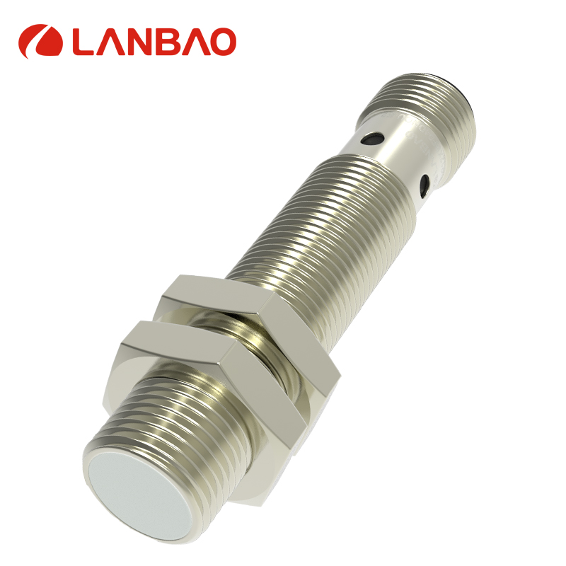
Figure 1. Official Lanbao M12 Factor 1 product image. Match the selected output and connection suffix to the released bill of materials. Source [1].
How standard inductive sensing responds to metal
An inductive sensor creates an electromagnetic field near its sensing face. A conductive target changes the behavior of that field, and the electronics detect the resulting change. The response depends on the sensor design and the target's electromagnetic properties as well as geometry. Conductivity and magnetic permeability both matter; simply describing a target as “metal” is not sufficiently precise for selection.
The rated distance is established under defined reference conditions. Manufacturers may provide correction or reduction factors for other materials. A factor below one indicates a shorter distance relative to the specified reference response. The factor is not a universal property of aluminum, copper, or stainless steel independent of the sensor.
For example, one Pepperl+Fuchs standard inductive model lists reduction factors of 0.4 for aluminum and 0.25 for copper. [2] Those values illustrate the potential scale of variation; they must not be copied into a different supplier's specification. The right question is which factors apply to the exact part number and the actual target.
What Factor 1 changes and what it leaves unchanged
A Factor 1 design compensates for material-dependent behavior so its listed metals can be detected at approximately the same distance. The implementation varies among manufacturers. An ifm Factor 1 datasheet, for example, lists a correction factor of one for steel, stainless steel, brass, aluminum, and copper. [3] Another product may define its material list and allowed variation differently.
Factor 1 is therefore a design capability rather than a promise of perfect equality under every condition. It does not imply unlimited range, zero drift, or identical behavior for arbitrarily small targets. It also does not convert an inductive presence sensor into a material analyzer. A single switching output generally indicates whether the target meets the switching condition, not which alloy is present.
|
Selection issue |
Standard inductive sensor |
Factor 1 inductive sensor |
|
Mixed metal range |
May require material correction factors |
Designed for similar range on listed metals |
|
Fixed steel target |
Often a straightforward candidate |
May add little value if no other benefit is needed |
|
Alloy change |
Requires margin review and testing |
Still requires verification of supported alloys |
|
Small or curved target |
Geometry can reduce usable range |
Geometry remains relevant |
|
Welding environment |
Requires explicit immunity specification |
Factor 1 alone does not establish immunity |
|
Setup management |
Material changes may require adjustments |
Can simplify a common mounting arrangement |
Calculate the available gap before comparing prices
Use a first-pass calculation to reveal candidates that lack margin. In an illustrative comparison, a standard sensor has a nominal reference distance of 8 mm and a model-specific aluminum factor of 0.4. Multiplying gives approximately 3.2 mm under comparable reference conditions. This is a screening estimate, not an assured installation limit.
If the machine permits the target gap to increase to 4.0 mm, that candidate already looks unsuitable without a design change. A Factor 1 candidate with adequate verified range may remove the material-related shortfall. Alternatively, a larger standard sensor, a closer bracket, or a different target flag could solve the application at lower overall cost.
Next, build the mechanical stack. Suppose the nominal gap is 2.0 mm, bracket tolerance adds 0.3 mm, target-position variation adds 0.4 mm, and runout adds 0.2 mm. The illustrative maximum gap is 2.9 mm. Against a published assured limit of 3.06 mm, the remaining difference is only 0.16 mm. That is a small allowance for unmodeled movement, wear, or target differences and deserves engineering review.
Do not automatically apply the same correction twice. Ask whether an assured-distance claim already includes material effects, voltage, temperature, and manufacturing tolerances. Where the documentation is unclear, request written clarification and validate the intended range. Also check the minimum gap so vibration or overtravel cannot bring the target into contact with the sensing face.
Match target size and mounting conditions
Published sensing distances typically use a defined target. The Lanbao M12 page identifies an iron reference target of 12 × 12 × 1 mm. [1] A narrow screw head, thin foil, perforated tab, or curved tube is not equivalent to that reference plate. A small target may interact with only part of the field, reducing the usable detection distance.
Record the actual alloy designation and dimensions. “Stainless steel” is a family of materials, and production processes can change magnetic behavior. Coatings and surface layers may also alter the effective separation or target response. Trial samples should include accepted material and thickness extremes, rather than only the nominal drawing condition.
Flush sensors are intended for specified mounting arrangements with surrounding metal. Non-flush designs generally require more clearance around the active face. Follow the selected model's installation drawing, including protrusion, free zones, and spacing from neighboring sensors. A correct material choice cannot compensate for an installation that distorts the sensing field.
Keep switching behavior separate from detection distance
Hysteresis is the difference between the switch-on and switch-off positions. It helps prevent rapid output chatter around a threshold, but it also affects release position and the minimum gap between successive targets. Repeatability describes how consistently the switching point returns under defined conditions. Neither specification replaces the need for a sufficient operating margin.
For an illustrative conveyor, target pitch is 20 mm and speed is 1 m/s. The sensor encounters 50 targets per second. That frequency is only the beginning of a timing check. A 2 mm target offers about 2 ms of passage time before considering field geometry, while the control system may apply an input filter that is longer than the usable pulse.
Measure actual output pulses at maximum speed and verify the PLC receives them. Check both activation and release, especially where closely spaced targets can merge into a continuous signal. A high catalog switching frequency does not prove that a particular short target, mounting arrangement, and controller configuration will work together.
Verify electrical and environmental compatibility
Select NPN or PNP to match the PLC input circuit and confirm normally open or normally closed behavior. Verify the connector pinout, operating voltage, output current, residual voltage, and leakage limits where applicable. A matching thread size and connector shape do not establish electrical interchangeability.
Treat magnetic-field resistance as a separate performance requirement. Welding, induction heating, and high-current conductors can create conditions that demand dedicated validation. Likewise, an IP rating describes enclosure protection under specified tests; it does not establish resistance to every coolant, cleaning chemical, hot chip, or high-pressure washing process.
Define the operating environment at the sensor location rather than using room temperature alone. A sensor near a heated fixture may experience a different temperature from the control cabinet. Include cable flexing, strain relief, vibration, and maintenance access in the selection review. The cable or connector can become the practical failure point even when the sensing electronics remain suitable.
Run a mixed metal qualification trial
Create a test matrix that mirrors the released product variants. The suggested checks below are an application qualification plan, not a claim that a particular standard mandates these sample quantities or acceptance thresholds.
|
Test variable |
Suggested trial coverage |
Release evidence |
|
Material |
Every approved alloy and supplier variation |
Switching margin by actual material |
|
Target geometry |
Minimum area, minimum thickness, maximum curvature |
Verified worst performing target |
|
Installation gap |
Minimum, nominal, maximum stack positions |
No contact and reliable detection |
|
Motion |
Startup, nominal, maximum speed, smallest spacing |
Pulse capture and missed detection count |
|
Environment |
Expected temperature and interference extremes |
Stable operation with recorded conditions |
|
Replacement |
Multiple units and a realistic maintenance swap |
Settings and bracket reproducibility |
1. Freeze the sensor model, drawing revision, output, and mounting position.
2. Measure activation and release distances for each representative target.
3. Repeat the measurements to quantify variation rather than recording one successful trigger.
4. Run production motion and capture the signal at the controller.
5. Investigate failures by changing one factor at a time.
6. Release the model only after the agreed margins and timing requirements pass.
Keep failure observations in the report. A trial in which every difficult target was removed until the sensor passed is not representative qualification. If a bracket change solves the problem, repeat the affected tests and update the installation drawing so later machines receive the same geometry.
Decide using lifecycle cost and standardization needs
For one fixed steel target with generous clearance and stable conditions, a standard inductive sensor may be entirely appropriate. For a platform serving multiple metal variants, Factor 1 can reduce setup changes, spare-part complexity, and the risk of a replacement being fitted at the wrong distance. The economic benefit depends on the actual workflow.
Use an illustrative cost model rather than assuming a premium always pays back. If a sensor option adds 20 currency units at 20 sensing positions, the hardware premium is 400. If it genuinely avoids four one-hour changeovers valued internally at 150 per hour, the modeled benefit is 600 before implementation and validation costs. These are hypothetical inputs, not supplier prices or promised savings.
For a Lanbao evaluation, reference the M12 Factor 1 page and ask for the selected part number's confirmed installation and application data. [1] An RFQ should include the target matrix, gap stack, electrical requirements, timing, environment, and required trial evidence. That information allows the supplier to propose a defensible solution rather than quoting on diameter alone.
References
[1] Lanbao M12 Factor 1 sensor specifications part numbers and image source
[2] Pepperl Fuchs NMB10 18GM55 E0 example of model specific reduction factors
[3] ifm IIS291 datasheet listing material correction factors and switching deviations
Frequently Asked Questions
Does Factor 1 mean exactly the same distance for every metal
It means the sensor is designed for similar response across its specified metals. Check the allowed variation, reference target, and operating conditions. It does not guarantee identical detection for every alloy, thickness, or shape.
Can a standard inductive sensor detect aluminum
Many can, but the usable distance may be shorter than for the reference steel target. Use the exact model's aluminum data and verify the actual part at the maximum installation gap.
Is Factor 1 always the better purchase
No. A stable application using one material may gain little from material compensation. Compare detection margin, mounting constraints, electrical compatibility, reliability evidence, and lifecycle cost for the actual machine.
Can Factor 1 sensors distinguish copper from steel
A conventional Factor 1 switching sensor is intended to detect different metals consistently, not identify them. Metal sorting requires a sensing system explicitly designed and validated for material discrimination.
Can I install a 4 mm sensor at a 4 mm gap
Not from the rated value alone. Use the specified assured operating distance and account for target geometry and mechanical variation. A nominal installation at the range boundary leaves little or no practical margin.
Are all Factor 1 sensors suitable near welding equipment
No. Check the explicit magnetic-field immunity, weld-spatter protection, temperature limits, and cable suitability. Validate the sensor with the welding process operating because material compensation is a separate capability.
What should an RFQ include for mixed metal detection
Include each alloy, target size and thickness, gap tolerances, mounting drawings, speed, target spacing, PLC input type, supply, connector, and environment. Ask the supplier to identify the worst-case target and support the proposed operating margin.
Post time: Nov-11-2026